Configuring and Activating the Versa Device
Versa SD_WAN provides you multiple options to activate Branch CPEs across customer deployments sites. Use any of these options to address your use case scenario:
Global-Activation Zero Touch Provisioning (ZTP)
URL Based Zero-Touch Provisioning (URL_ZTP)
Web Portal Based Auto-Provisioning
CLI Based Auto-Provisioning
Global-Activation Zero Touch Provisioning (ZTP)
This section covers:
Global Activation ZTP
Instructions to Onboard Branches for Global-Activation
Debugging Failures on the Branch-Device Web-UIs
Global Activation ZTP
Versa device activation or ZTP lets you connect the branch device to the network and power it on. The default configuration is added as part of the Versa FlexVNF software installation. After switching on and establishing an internet connection, the device calls home to a cloud hosted Versa-Staging controller. This staging-controller redirects the branch-device to the Staging-Controller hosted by the provider (Service-Provider or Enterprise).
The CPE device follows these stages:
Versa Pre-Staging—Based on input from the distributor, an entry is created in the inventory for each device using the device serial number. The FQDN or IP-address of the provider’s Staging Controller is added to the device. The CPE device connects to the Versa Staging Controller and is redirected to the provider’s Staging Controller.
Provider Pre-Staging—The provider claims the device and prompts for a 2-factor authentication and redirects the branch-device to the Staging controller. You can skip this stage if the distributor has knowledge of the provider’s Post-Staging Controller.
Provider Staging and Post-Staging—If you skip step 2, then functions like claiming the device is done here. The providers can onboard Customer’s (Tenants) here. IKE comes upon provider and customer tenants.
The branch device reboots at the end of each step before moving on to the next step.
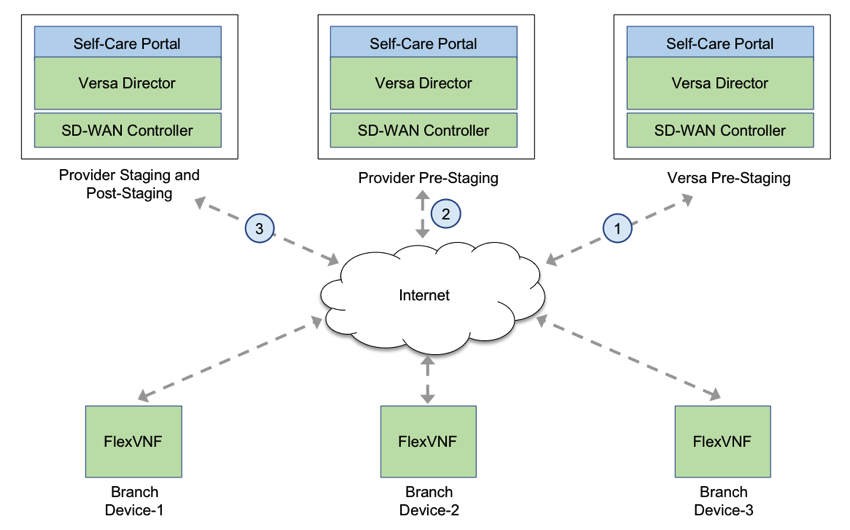
Figure 1: Global-Activation Zero Touch Provisioning
Refer Figure 2 Versa Device Activation Call Flow for more information about the device activation call flow. The device goes through the Versa Pre-Staging and Provider Post-Staging phases. As mentioned, you can skip the provider’s Pre-staging to avoid an additional reboot.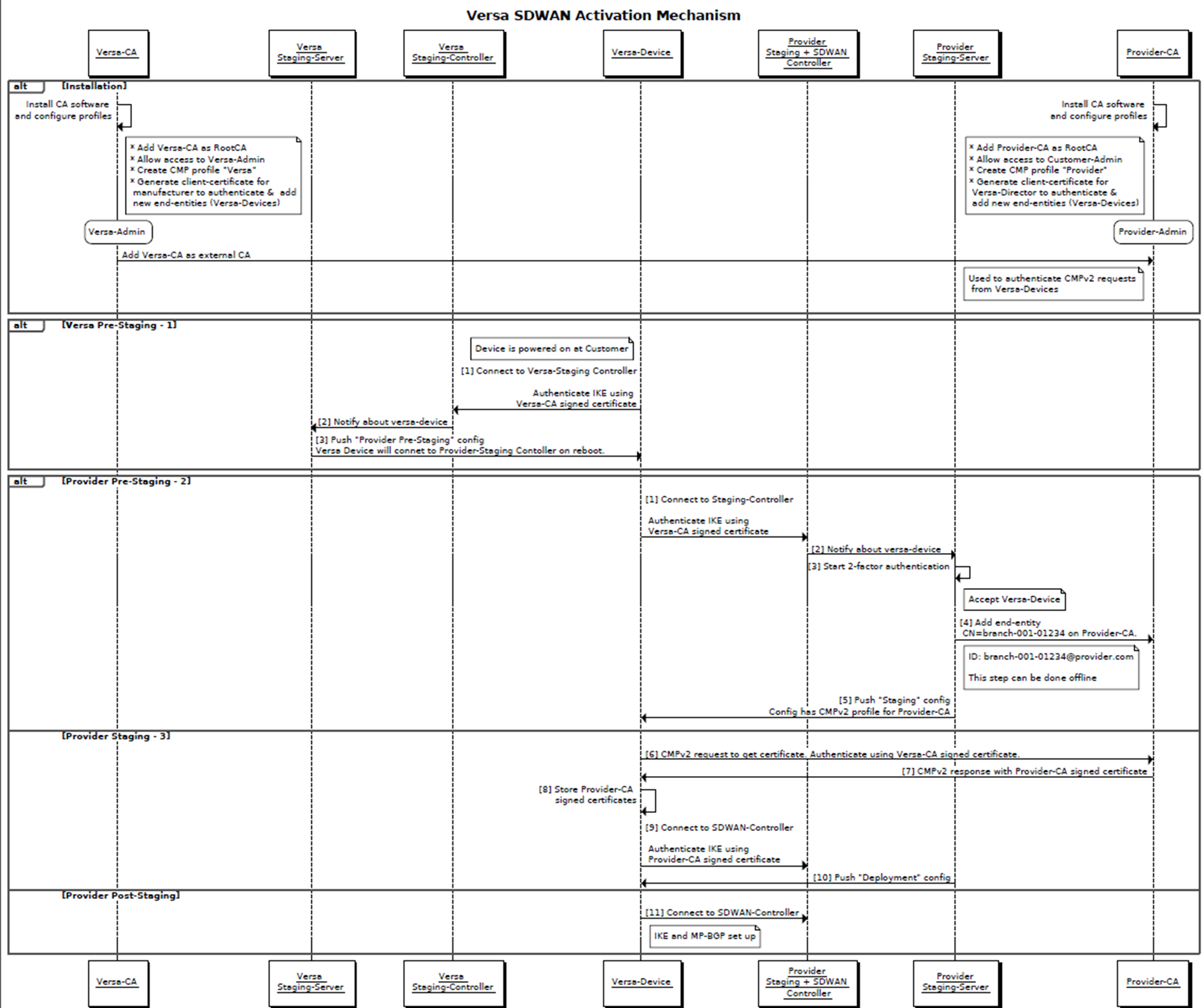
Figure 2: Versa Device Activation Call Flow
In the Provider-Staging stage, use either PSK or PKI to authenticate the branch device. Figure 2 illustrates how to authenticate using PKI.
Refer to Instructions to onboard branches for Global-Activation for additional information to provision the branch device on the Versa Staging Director.
Instructions to Onboard Branches for Global-Activation
This section provides information about onboarding the branch-device using the Versa Director.
Onboarding the Branch-Device Using Versa Director
Follow these instructions to Onboard the branch-device using Versa Director:
Login to the Cloud-Hosted Versa-Director.
A Versa-Public Controller is created for branches to connect. The branch-device’s factory-default configuration automatically (once the device has internet connectivity) connect to this controller. It uses PKI to authenticate and sets up an IKE based IPSec tunnel.
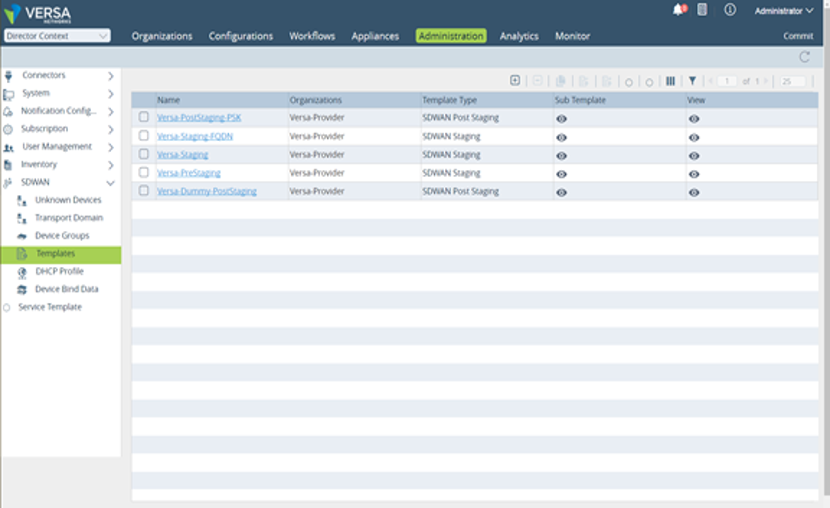
Use any of these pre-created templates to help associated bind-data with on boarding the branch-devices.
Versa-PreStaging—Use this when the device has to go through another Pre-Staging Controller. Bind-data includes Global-tenant-Id, Pre-Staging-Controllers PSK Auth Parameters, and Pre-Staging-Controller’s IP-Addresses.
Versa-Staging—Use this when the device has to go directly to Post-Staging Controller and the IP-Address of the controller is known. Bind-data includes Global-Tenant-Id, Staging-Controllers PSK Auth Parameters, and Staging-Controller’s IP-Addresses.
 You can modify the Versa-PreStaging, Versa-Staging and Versa-Staging-FQDN templates per provider. Create a different device-group and associate the template with it.
For example, a provider can use a different local auth parameter for all its branches instead of using the default or use a separate local auth parameter per branch.Versa-Staging-FQDN—Use this when the device needs to go directly to Post-Staging Controller and the FQDN of the controller is known. This is the most common use-case. Bind data includes Global-Tenant-Id, Staging-Controllers PSK Auth Parameters, Staging-Controller’s FQDNs.
Versa-Dummy-PostStaging—Placeholder since devices will not be attempting PostStaging with this Controller/Director.
These Device-Groups are pre-created to help on board the branch-devices.
Versa-PreStaging-DG—If the device needs to go through another Pre-Staging Controller.
Versa-Staging-DG—If the device needs to go directly to Post-Staging Controller and the IP-Address of the controller is known.
Versa-Staging-FQDN-DG—If the device needs to go directly to Post-Staging Controller and the FQDN of the controller is known. This is the most common use-case.
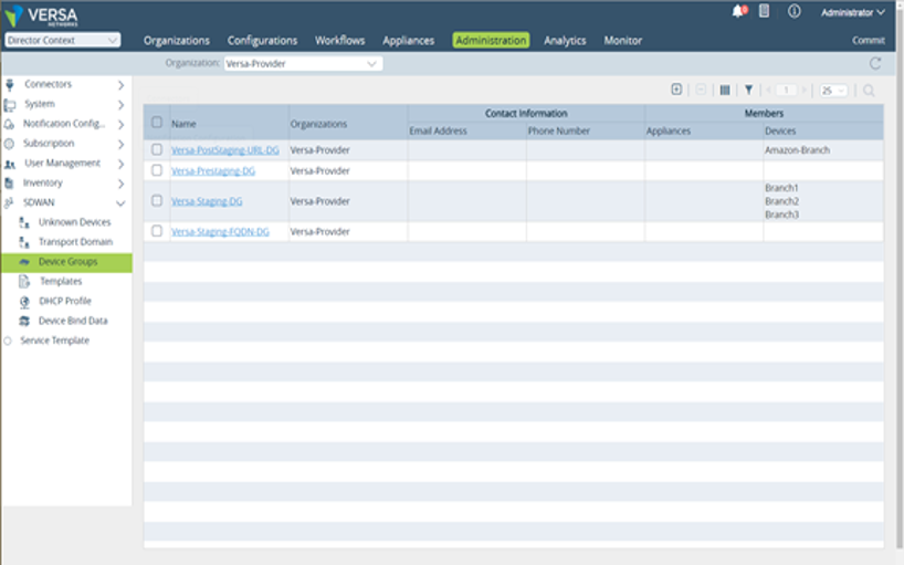
The templates are associated with the device groups. As an example, the Versa-Staging-DG device group is shown.
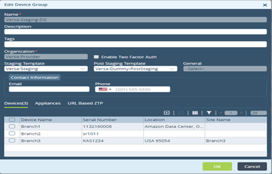
Use Workflows to onboard the device. The manufacturer provides Versa with a list of chassis-ids shipped to a provider.
 Use the serial number of the box as the devices chassis-id.
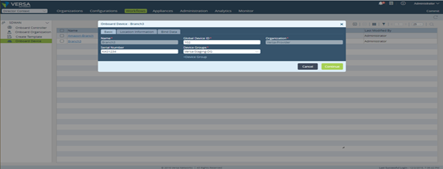
Versa will contact the provider and get the Staging-Controller information along with the tunnel auth parameters.
 This is a one-time activity that happens before any device is shipped or provisioned.
Continue to enter the Location-Information and Bind-Data of the Staging-Controller.
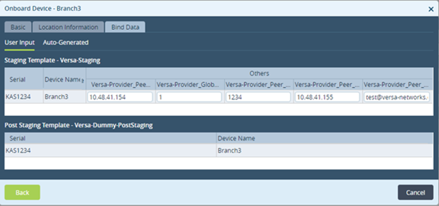
 You have to configure all the fields in this window.
Refer to this table to configure the Bind data user inputs:
Field | Description |
Versa-Provider_Peer_WAN1_IP | This is the controllers WAN IP address. |
Versa-Provider_Global_Tenant_Id | This is the tenants ID used for identifying a tenant. |
Versa-Provider_Peer_Auth_Key | This is the controller’s authentication key used for authenticating the tunnel between the controller and the branch. |
Versa-Provider_Peer_WAN2_IP | This is the controllers WAN IP address. |
Versa-Provider_Peer_Auth_Id | This is the controller's ID string used for authenticating the tunnel between the controller and the branch. |
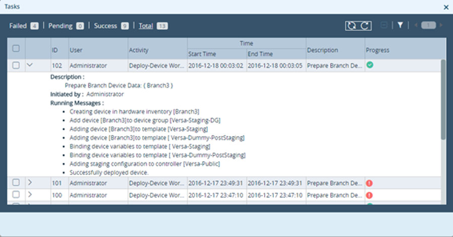
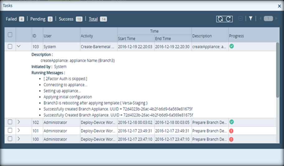
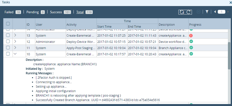
Once deployed, the Versa-Director’s Tasks confirms the successful deployed of the device.
Identifying Branch-Device on Versa-Public CA
Follow these steps to identify the brach-device on Versa-Public CA:
The branch-device by default will try to fetch certificates from the Cloud-Hosted Versa-Certificate-Authority. In the current release, an End-Entity entry should be added in the CA for issuing the certificate. In the next release, a CA connector will be added in the Versa-Director which will automatically create an entry in the CA as part of onboarding a device.
Login to the Versa-CA. A browser certificate is required for logging in.
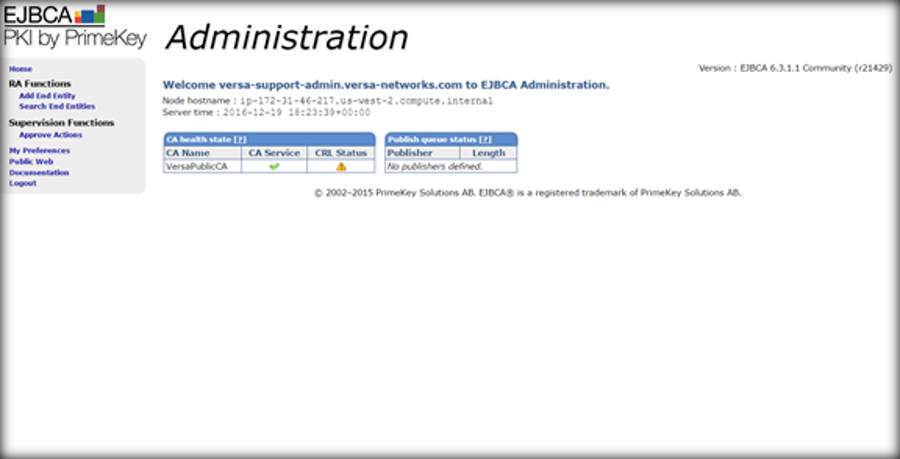
Refer to the Google's website for information on adding a certificate to the Chrome web-browser.
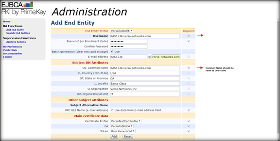
Add an end-entity using the VersaPublicEE profile. It is important to note that the Username and Common Name should be same.
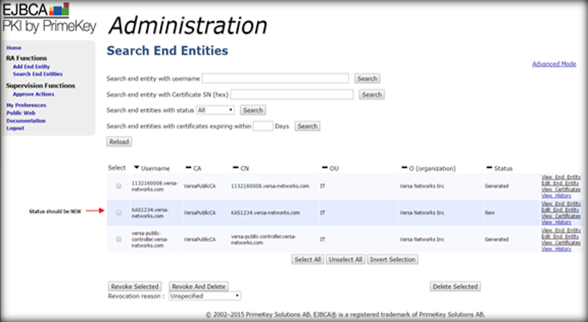
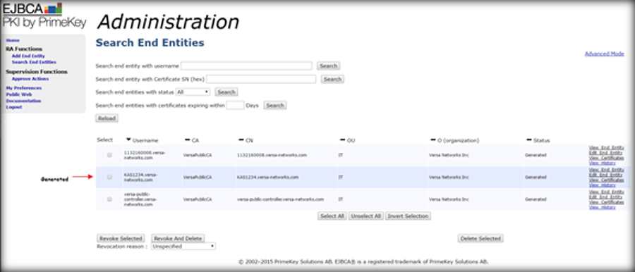
The summary of the added users can be seen using the Search End Entities Option. The status of the device will show:
New—If the certificate has not been issued yet.
Generated—If the device connected and fetched a certificate.
Revoked—If the CA revoked certificate (an already issued certificate) for this device.
 Click Edit to change the state of an entity from Generated to New to change the status of the device. Do this only when you want to re-provision the device again.
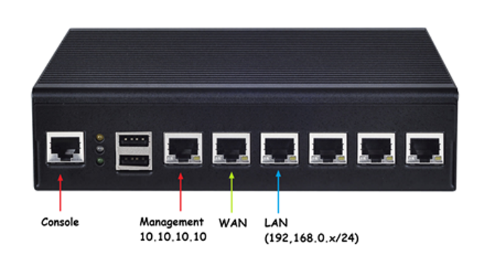
For device activation, the ports are preconfigured. Once, the device is activated, the next-stage configuration can change the port assignment. The WAN port on the branch device needs to be plugged to the internet to connect to the Versa-Director.
The device will try to fetch the certificate from the Versa-CA. The CA should show that it has issued a certificate.
 Refer to Step 6 Activating Versa Device in URL Based Zero-Touch Provisioning (URL-ZTP) for two-factor authentication.
The device will setup IKE based tunnel with the Versa-Public Controller. The controller will notify the Versa-Director of the new device and based on the bind-data, new configuration will be pushed to the device.
Debugging Failures on the Branch-Device Web-UI
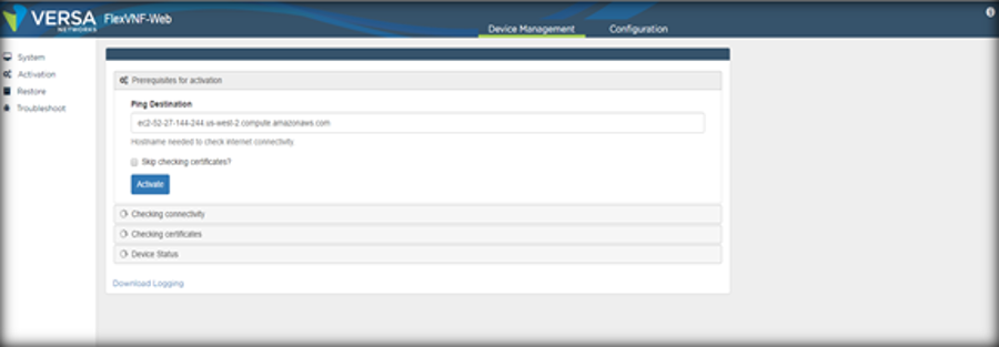
If there are failures, the installer can connect a laptop to the LAN port of the device and troubleshoot the failure. The laptop should receive an address in the 192.168.0.x/24 from the DHCP server running on the LAN interface.
On the laptop, open a browser and type http://192.168.1.1:80
Login with the provided default credentials and click on the Activation tab. Hit “Activate” button.
The activation process will:
Try to ping the Versa Public Controller’s FQDN.
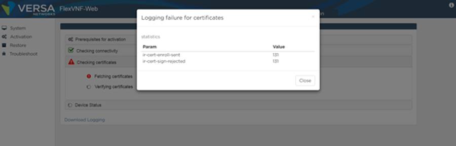
Check if the certificate is fetched from the Versa Public CA. Shows failed statistics.
Check the status of IKE tunnel. Shows failed statistics.
For example, if the connectivity test passed and certificate fetching failed, the “View failure” will show up. Clicking on it will pop-up the failure statistics.
URL Based Zero-Touch Provisioning (URL-ZTP)
This section covers:
URL ZTP
Adding a URL ZTP for a New Device Group
Enabling URL Based ZTP on an Existing Device-Group
Onboarding and Deploying Versa Devices
Editing URL ZTP Parameters
Accessing the URL to Activate a Versa Device
Activating Versa Device
Debugging Instructions for Site Administrators to Start Using the URL Based ZTP
Debugging Instructions for SEs to Demo and Test the URL Based ZTP
URL ZTP
In addition to Zero-Touch Provisioning described above, Versa supports site administrator assisted URL based Zero-Touch Provisioning. These are the two advantages of this feature:
Decouple a particular hardware (chassis-id) from a branch location i.e. bootstrap any hardware running an appropriate Versa FlexVNF software.
Allow device activation directly to Post-Staging Controller i.e. it can choose to go through the staging process and skip the pre-staging process (Versa Pre-Staging and Provider Pre-Staging).
In this approach, a URL is created to bootstrap the device when it on-boards. This URL is sent to northbound AMQP server. You can also access this URL from the Versa Director using REST APIs.
The onsite installer can connect their laptop to the LAN port on the Versa branch-device to access the internet and check the email sent from the administrator managing the Versa Director to access the URL. Versa device runs a DHCP Server on the LAN port on the factory default device.
 URL based ZTP supports on both bare metal and virtual environment.
Run the default configuration script In bare metal environment.
Load the default-device.cfg in virtual environment.
Adding a URL ZTP for a New Device Group
You can create device groups to logically group devices based on their location and type. Creating groups help in defining policies for the group. Follow these steps to add a new device group with URL ZTP configured for it.
Select the Director Context > Workflow tab > Add Device to configure URL ZTP per device-group.
Enter these details in the Add Device window:
Use this field… | to … |
Basic Tab | |
Name | Enter the name of the device that you want to add to the organization and to the device group. |
Global Device ID | The system auto-generates the value with the next available ID. |
Organization | Select an NMS organization from the Versa Director. |
Serial Number | Click Generate Serial Number to auto generate and auto populate the chassis/device ID.
|
Device Groups | Select a ZTP enabled device group and associate the device to it. |
 The Generate Serial Number button appears only when you select ZTP enabled Device Group.
Click +Device Group to configure the URL based ZTP to the group. This opens the Create Device Group window.
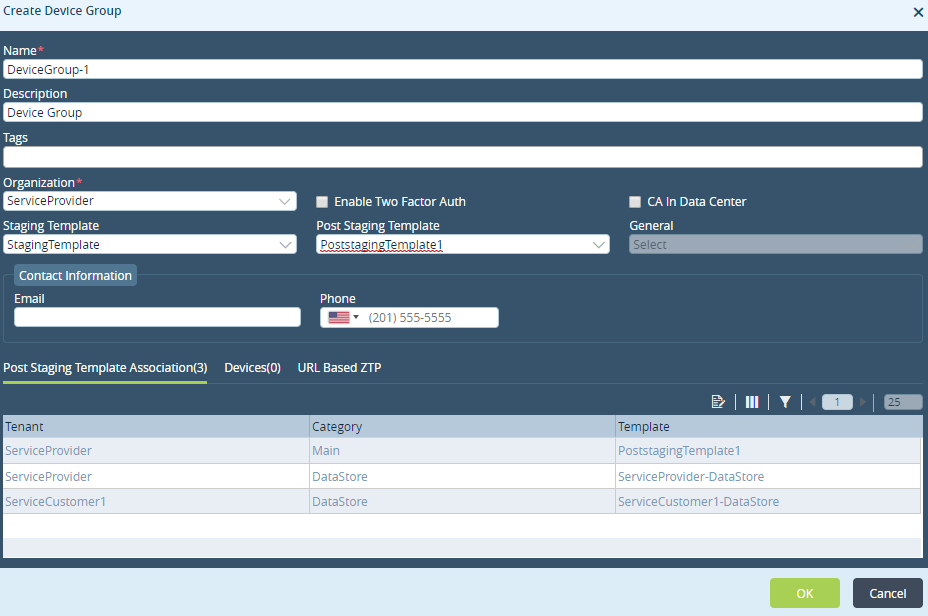
Enter these details in the Create Device Group window:
Use this field… | to … |
Name | Enter the name of the device that you want to add to the organization and to the device group. |
Description | Enter a brief description of the device group and its purpose. |
Tags | Enter a tag to identify the device group. |
Organization | Select an NMS organization from the Versa Director for this device group. |
Enable Two Factor Auth | Select this to enable two-factor authentication. This enables the email and phone field in the Contact Information panel. A red asterisk appears over these two fields. You get notified via an email when a branch performs Zero Touch Provisioning ( ZTP). You have to click the authentication mail to allow URL based ZTP. |
Staging Template | Select a staging template for the device. |
Post Staging Template | Select the post staging template for the device. |
General | Select this template when using vCPE devices. |
Contact Information | This information is used for Two Factor Auth.
|
URL Based ZTP tab | |
URL Based ZTP | Select this to enable the URL Based ZTP for the device group.
|
5. Click OK to add a device group with URL ZTP configured on it.
Enabling URL Based ZTP on an Existing Device-Group
You can also configure URL based ZTP on an existing device group. Follow these steps to enable URL ZTP per device-group:
Select the Director Context > Administration tab > SDWAN > Device Groups and select an existing device group on to configure the URL based ZTP. This opens the Edit Device Group window.
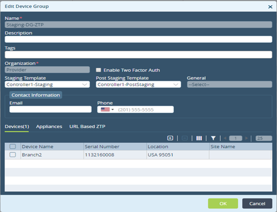
- Select a Staging Template or Post Staging Template for the device.
Select the URL Based ZTP tab in the Edit Device Group window and enter these details:
Use this field… | to … |
URL Based ZTP Tab | |
URL Based ZTP | Select this to enable the URL Based ZTP for the device group.
|
Click OK to save the changes and enable URL based ZTP on an existing device group.
Onboarding and Deploying Versa Devices
Versa Director provides workflows to onboard devices. Follow this workflow to onboard a device:
Select Director Context > Workflow tab > Deploy Controller to add a controller. Refer to Onboarding Controllers in the Versa Software Defined WAN Configuration Guide for more information.
Select Workflow tab > Create Organization to add and associate an organization with the controller. Refer to Onboarding Organizations in the Versa Software Defined WAN Configuration Guide for more information.
Select Workflow tab > Create Template to provision a staging and post staging template and associate it with a branch group. Refer to Creating Templates in the Versa Software Defined WAN Configuration Guide for more information.
Select Workflow tab > Add Device to onboarding a branch device. Enter all the associated parameters for each branch device. Refer to Onboarding Devices in the Versa Software Defined WAN Configuration Guide for more information.
For URL based ZTP:Select the + Device Group from the Add Device window.
Select the Basic tab and generate a serial number for the device that is associated with a ZTP enabled device group.
Click the +Device Group to open the Create Device Group window.
Select URL Based ZTP tab and:
Select the URL Based ZTP checkbox to enable URL Based ZTP for the device.
Select either Pre Staging or Post Staging option for using URL based ZTP.
Select the Controller to which this device belongs.
Select the VPN Profile to associate with the controller for IPSec authentication.
Select Location Information tab and enter the location related details and coordinates.
Select Bind Data tab and enter the device IP address and other related details.
Select the URL Based ZTP to check the auto-populated URL ZTP information.
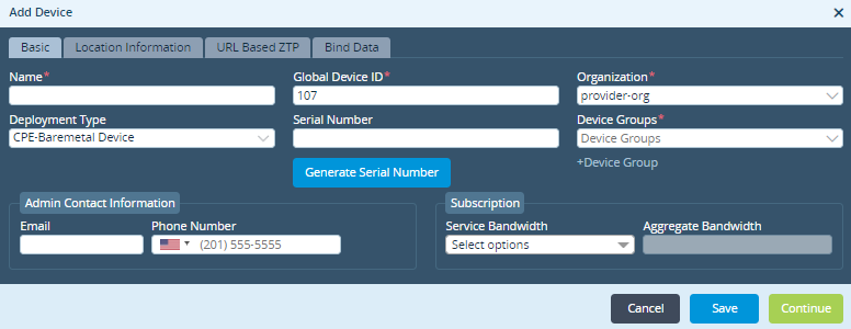
- Click Deploy to onboard and deploy the device.
Editing URL ZTP Parameters
After deployment, the CPE device is available in the Inventory. Follow these steps to edit the URL ZTP parameters:
Select Administration > Inventory > Hardware and select the CPE device to further customize the URL based parameters.
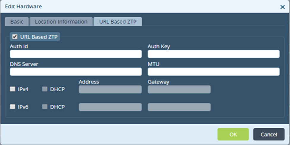
Make the changes in the Edit Hardware window.
Click OK to save the configuration.
Accessing the URL to Activate a Versa Device
Use one of these options to access the URL:
From the AMQP server configured on the Versa Director. The URL is posted to the AMQP server post the device onboarding and deployment.
Query the URL using Restful API. For example,
http://x.x.x.x:9182/vnms/sdwan/device-url-mappings/device-url-mapping/Branch2
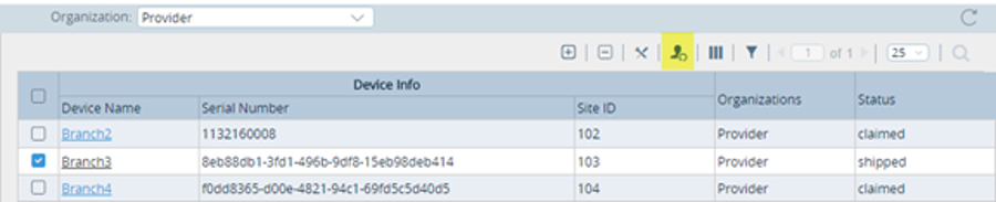
Copy the URL from Administrator > Inventory > Hardware window.
Select a Branch and click the highlighted option as shown in this image.
Activating Versa Device
The site administrator selects any CPE device that is running on the Versa FlexVNF and prepares it for deployment.
The site administrator has to follow these steps to activate the Versa device:
Connect their laptop to the LAN port on the Versa branch device to bootstrap the device.
Enter http://192.168.1.1:80 in the web browser to access the default login page. The device has a DHCP and Web Server running on 192.168.1.1.
 Versa recommends you to use Chrome (version 36 and above) to access the Device Management page.
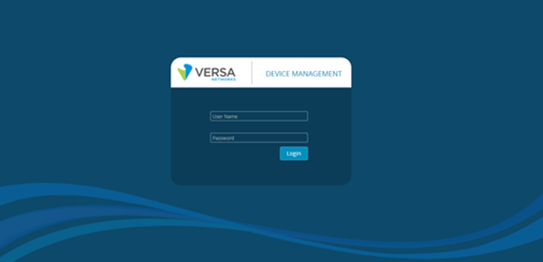
Use these credentials to login to the device management window:
Username—admin
Password—versa123
Connect the WAN port to the internet to access the email and get the the URL to bootstrap the device.
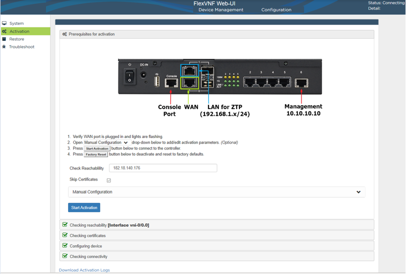
Use port 2 to connect to the internet.
Use port 3 to connect the laptop.
Access the email and get the URL.
4. Click on the URL in the email or paste the URL in the web browser and initiate the device activation process.
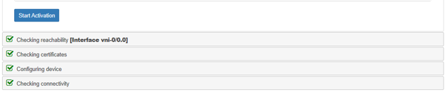
5. Click Activate to start the ZTP configuration on the device.
The device then:
- Checks for internet connectivity.
Fetches and checks valid certificates, if PKI based authentication is selected.
Uses parameters in the URL to connect to the right Staging-Controller.
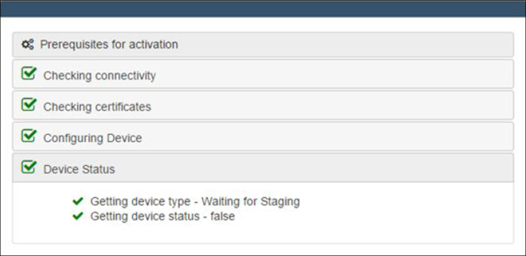
6. (Optional) Claim your device If you have enabled two factor authentication. Follow these steps to claim your device:
Click Claim Device when the device boots up for the first instance.
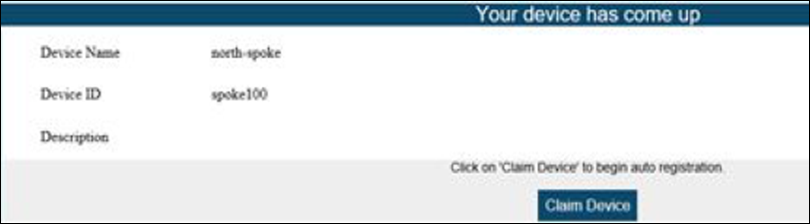
After claiming the device, you will receive the device registration code over an email or mobile phone, based on the option selected for delivering the registration code.
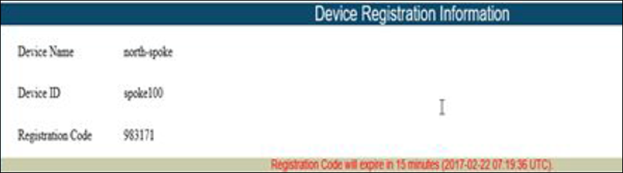
- Enter the registration code to complete the two factor authentication process.
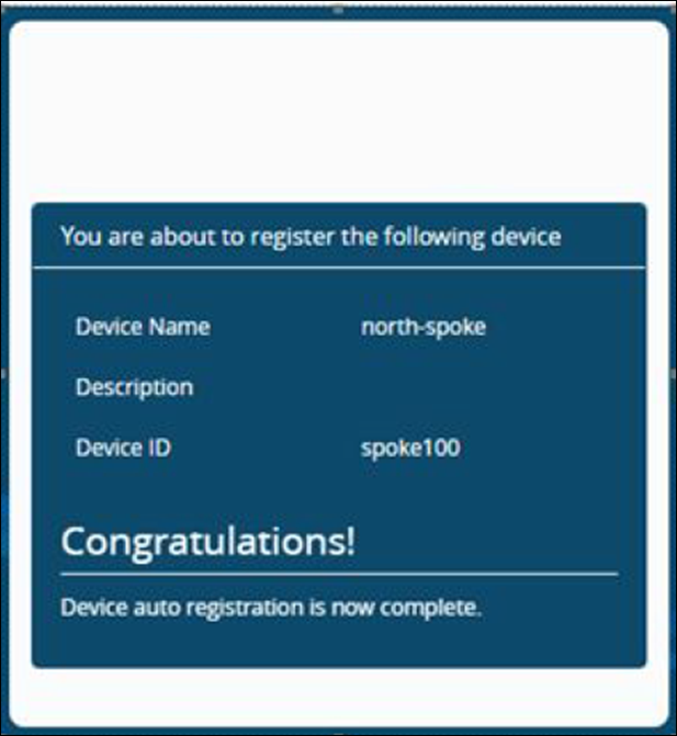
7. The device reboots on completion of ZTP.
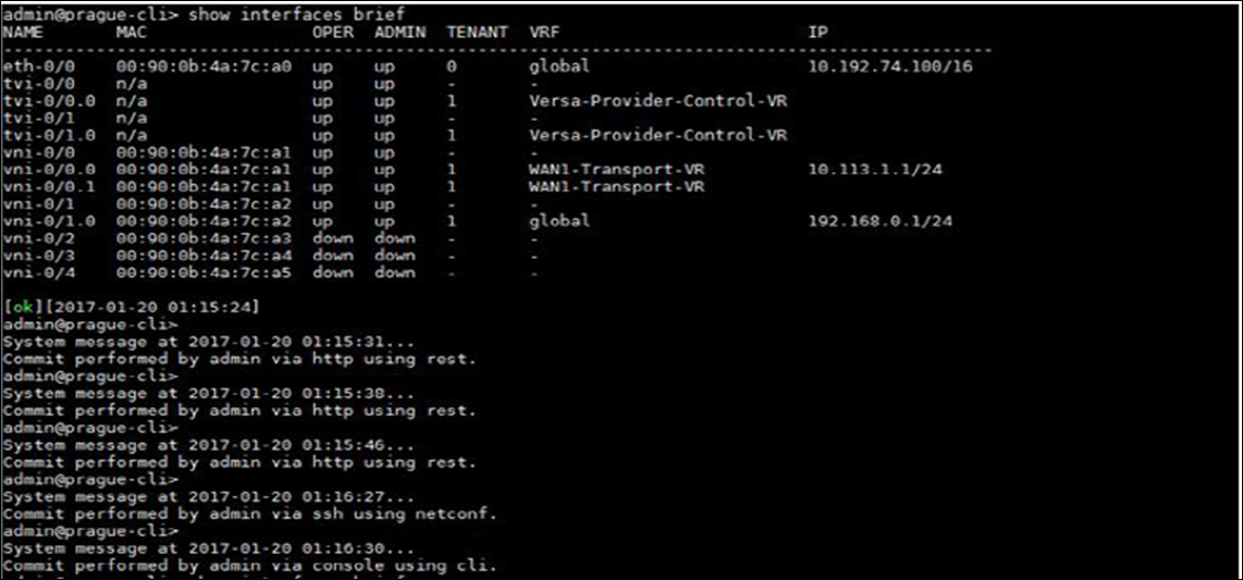
8. Verify the device activation status on Versa Director.
Versa Appliance UI allows you to program static IP addresses and DNS servers using the URL. YOU can also manually configure the address and DNS servers from the Configuration tab.
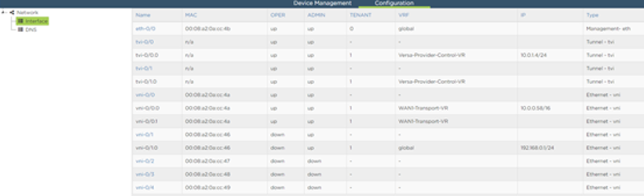
Debugging Instructions for Site Administrators to Start Using the URL Based ZTP
Follow these instructions to use URL Based ZTP:
Port 1 is eth0.
On Port 2, allocate a WAN IP. It will be empty if not connected.
Also, note that the default gateway in the global routing instance should be via the WAN port.
On Port 3, the LAN IP is received via DHCP. Use http://192.168.1.1:80 to access the device or directly use the generated URL.
Paste the URL in the browser to get started with the bootstrap process.
Once done you can monitor progress on the Versa-Director.
Debugging Instructions for SEs to Demo and Test the URL Based ZTP
Follow these instructions to use demonstrate and test URL Based ZTP:
Install new .bin file. This is not required on a newly shipped device.
Run the /opt/versa/scripts/versadevice-factoryreset.sh file on the branch device to install the factory default configuration. This allows the laptop that you connect to the branch device to access internet.This is not required on a newly shipped device.
Run the show interfaces brief CLI command.
admin connected from 10.0.0.27 using ssh on versa-flexvnf
admin@versa-flexvnf-cli> show interfaces brief
NAME       MAC            OPER  ADMIN  TENANT  VRF IP
---------------------------------------------------------------------------
eth-0/0    00:90:0b:43:10:42  upup     0   global
vni-0/0    00:90:0b:43:10:43  upup     -   -
vni-0/0.0  00:90:0b:43:10:43  upup     1   global  10.0.0.23/16
vni-0/1    00:90:0b:43:10:44  upup     -   -
vni-0/1.0  00:90:0b:43:10:44  upup     1   global  192.168.1.1/24
 [ok][2016-08-19 14:50:55]
Continue with steps provided in the previous section to start using the URL based ZTP.
Web Portal Based Auto-Provisioning
Versa provides a Manual Form where the onsite installer can fill in the required parameters and provision the branch device.
These parameters are available in the manual form:
Serial Number. The default is set to Auto.
Branch Staging Type.
Controller IP-Address (IPv4/IPv6) and/or FQDN.
Global-Tenant-Id
Branch WAN Port IP-address.
DHCP
Static - IP address and gateway (IPv4 and/or IPv6).
Authentication Type (PSK/Certificate) to setup IKE with the controller.
Controller authentication parameters.
Branch authentication parameters.
Additionally, if a certificate needs to be fetched, options for CA and CSR parameters.
The user experience with this activation process is similar to the previously described ZTP activation methods.
 Refer to Step 6 Activating Versa Device in URL Based Zero-Touch Provisioning (URL-ZTP) for two factor authentication.
CLI Based Auto-Provisioning
This section covers:
Onboarding Versa Devices
Configuration Preparation on Branch
Sample Script with Arguments
Onboarding Versa Devices
Versa Director provides workflows to onboard devices. Follow this workflow to onboard a device:
Select Director Context > Workflow tab > Deploy Controller to add a controller. Refer to Onboarding Controllers in the Versa Software Defined WAN Configuration Guide for more information.
Select Workflow tab > Create Organization to add and associate an organization with the controller. Refer to Onboarding Organizations in the Versa Software Defined WAN Configuration Guide for more information.
Select Workflow tab > Create Template to provision a staging and post staging template and associate it with a branch group. Refer to Creating Templates in the Versa Software Defined WAN Configuration Guide for more information.
Select Workflow tab > Add Device to onboarding a branch device. Enter all the associated parameters for each branch device. Refer to Onboarding Devices in the Versa Software Defined WAN Configuration Guide for more information.
Once, the workflow has progressed to the last stage, the administrator can start onboarding branch devices, create device groups.
- Enter the device’s basic information in the Basic tab.

Click +Device Group to open the Create Device Group window. Add the required details.
Select Location Information tab to enter the devices locational information.
Select the Bind Data tab to enter the bind data related information.
Preparing a Branch Configuration
Use this configuration to prepare the branch:
admin@VNF:/$ sudo /opt/versa/scripts/staging.py -h
[sudo] password for admin:
usage: staging.py [-h] [-l LOCAL_ID] [-r REMOTE_ID] [-c CONTROLLER]
[-t {staging,prestaging}] [-d] [-w {0,1,2,3}] [-v VLAN]
[-s STATIC] [-g GATEWAY]
Setup branch staging config
optional arguments:
-h, --help        show this help message and exit
-l LOCAL_ID, --local-id LOCAL_ID
Local id-string/email
-r REMOTE_ID, --remote-id REMOTE_ID
Remote id-string/email
-c CONTROLLER, --controller CONTROLLER
Controller IP address (x.x.x.x)
-t {staging,prestaging}, --staging {staging,prestaging}
Staging type (default=staging)
-d, --dhcp        Use DHCP for WAN link
-w {0,1,2,3}, --wan-port {0,1,2,3}
   WAN port number
-v VLAN, --vlan VLAN  VLAN id
-s STATIC, --static STATIC
Static IP/mask for WAN link (x.x.x.x/y)
-g GATEWAY, --gateway GATEWAY
Default gateway IP address (x.x.x.x)
Sample Script with Arguments
To use this sample script:
Run the sudo /opt/versa/scripts/staging.py -l branch104@nms-org.com -r controller@nms-org.com -c 10.10.10.10 -t prestaging -w 0 -s 10.10.10.20/24 -g 10.10.10.10 script to onboard the branch-device.
 Refer to Step 6 Activating Versa Device in URL Based Zero-Touch Provisioning (URL-ZTP) for two factor authentication.
Check the Tasks window in the Versa Director to verify successful deployment of the device.
Security Considerations
These security considerations were considered for device bootstrapping:
The URL that is published is encrypted to avoid exposing the parameters that are required for configuring the branch device to initiate the bootstrapping.
Communication to the Staging-Controller is over IKE/IPSec. Each branch-device must authenticate with the Staging-Controller before completing the IKE. Use one of these to authenticate IKE:
Pre-Shared Key (PSK)—The local-auth and peer-auth parameters are sent via the URL. The parameters are not exposed because the URL is encrypted.
Public-Key Infrastructure(PKI)—Each device has a Versa-CA signed certificate. You can issue a Versa-CA signed certificate to the staging controller.
The controller runs Online Certificate Status Protocol (OCSP) to ensure that the branch issues a valid certificate. You can revoke the certificate, if the branch is stolen, to prevent the branch from connecting to the controller.
For subsequent IKE connections after staging the device, the provider can switch to its own CA-signed certificates.
In addition, the private key is never exposed in memory. It is protected by a TPM chip.
The staging process in itself does not last beyond a few minutes. IKE/IPSec rekey are not necessary. However, after staging the device, IKE/IPSec re-keys for control and data path connections. The rekey interval is configurable.
During staging, once the Versa Director is notified, a 2-factor authentication process ensures that the administrator permits the device to be staged.
You can add the device to device blacklist to prevent a rogue device from connecting to the controller. At any point, you can disconnect a rogue device from the network.