Link Aggregation Control Protocol (LACP) allows multiple physical Ethernet links to be bundled together into a logical Aggregate Ethernet (AE) interface, providing higher bandwidth, redundancy, and resiliency. In Versa Networks environments, AE interfaces with LACP can be configured either through a Device Template (recommended) or directly at the Appliance Context level.
Note:
AE interfaces cannot be configured using a Workflow Template, as workflows only provision service-oriented configurations and not base networking constructs like link aggregation.
WAN side limitation:
- AE cannot be attached to the WAN, instead, we can attach the AE to an IRB, and then it can be part of the SD-WAN WAN interface.
-We cannot do adaptive shaping or QoS configuration over IRBs.
This article walks through the methods of LACP configuration and provides additional considerations for network engineers deploying Versa Secure SD-WAN environments.
Why Use AE + LACP?
AE interfaces with LACP offer several operational benefits:
High Availability: Ensures traffic resiliency in case one physical link fails.
Load Balancing: Distributes traffic across multiple links, improving throughput.
Scalability: Provides flexible bandwidth expansion without redesigning network architecture.
Standardization: As an IEEE 802.1AX standard, LACP ensures interoperability with third-party switches, routers, and other networking gear.
Method 1: Configuring LACP Using a Device Template (Recommended)
The Device Template method is highly recommended because it provides centralized configuration management and scalable deployment across multiple appliances.
Step 1: Create a New Aggregate Ethernet (AE) Interface
In the Director view, navigate to:
Configuration > Templates > Device TemplatesSelect the device template to modify.
Go to:
Networking > Interfaces > AEClick + Add to create a new AE interface.
Enter the Aggregate Ethernet interface number (e.g., ae0).
Enable LACP and configure parameters:
LACP Mode
active: The device actively initiates LACP negotiation.
passive: The device waits for an LACP peer before enabling negotiation.
System Priority: Value between 1–65535 (default 127). Lower values have higher priority in LACP decisions.
Periodicity:
fast: Sends LACP PDUs every 1 second.
slow: Sends PDUs every 30 seconds.
Max Links: Maximum number of physical interfaces that can be bundled (default 16).
Click OK to save.
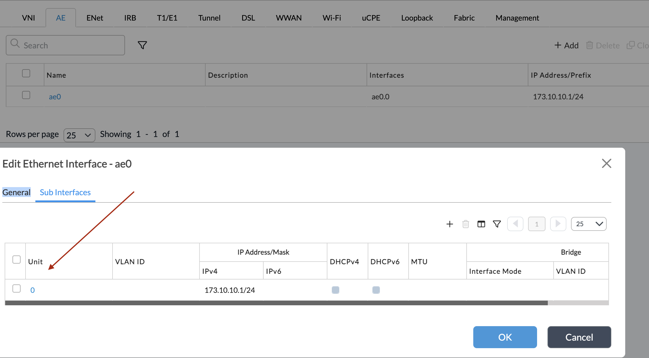
Step 2: Add Physical LAN Ports (Vni Ports) as AE Members
Go to
Networking > Interfaces > Ethernet.Click Add to configure a physical Ethernet interface.
In the Add Ethernet Interface window, select the Subinterfaces tab.
Click Aggregate Member.
Configure:
Interface: Select the AE interface you created (e.g., ae0).
LACP Priority: Determines member preference during link selection (default 127).
Click OK.
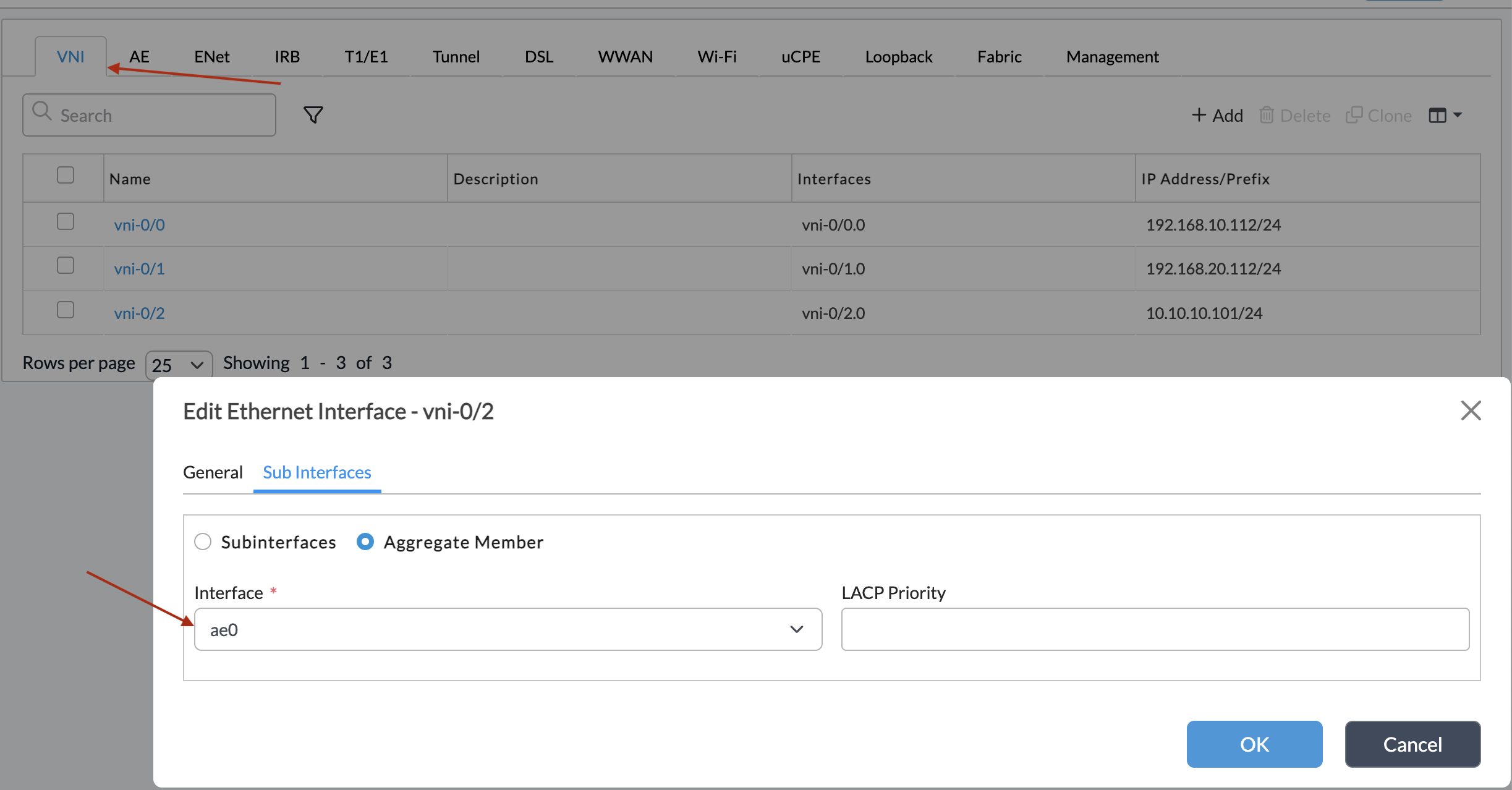
Repeat for all ports you want in the bundle.
Step 3: Assign AE Interface to Networks and Virtual Routers
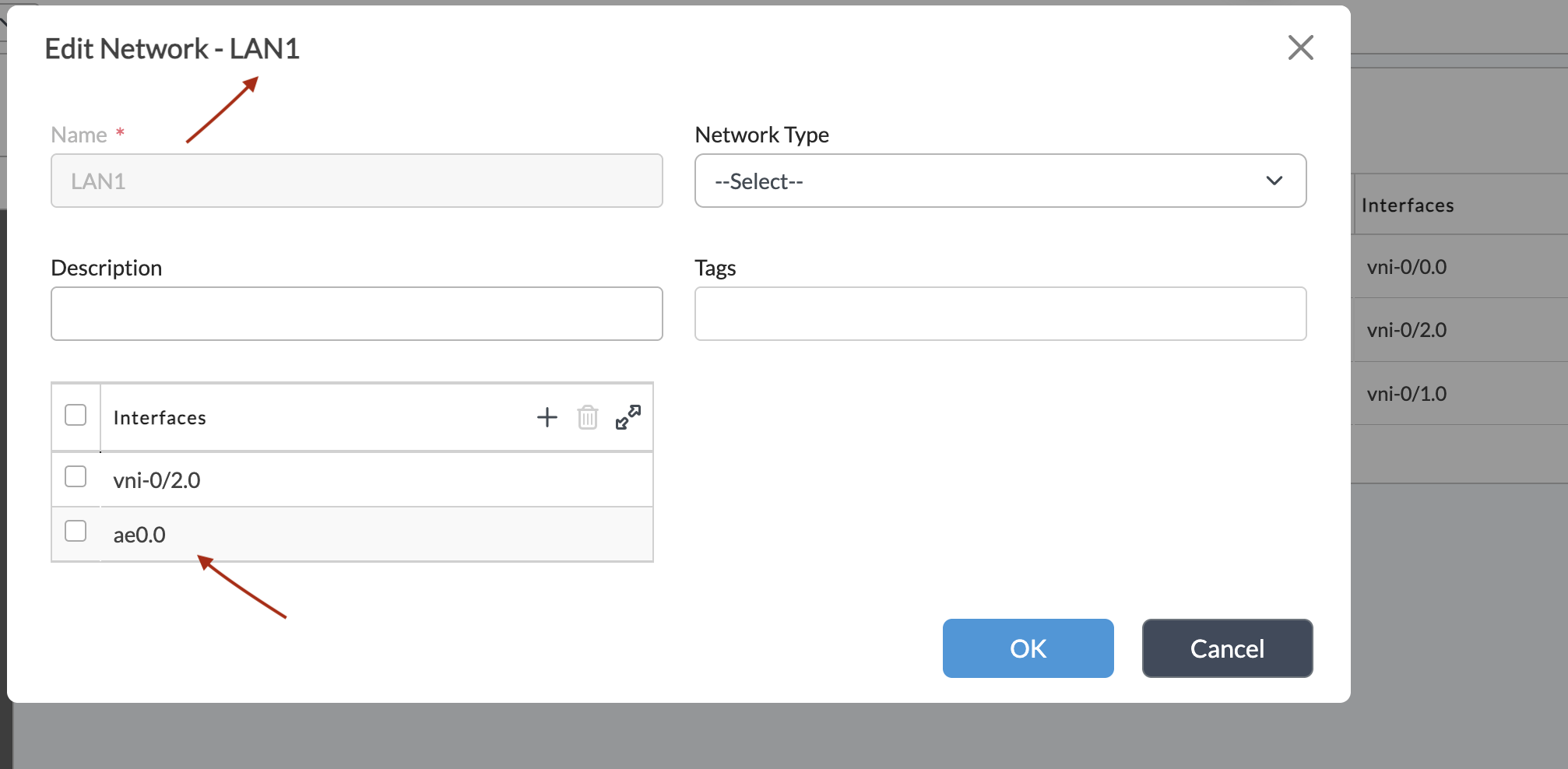
Navigate to the Networks tab within the device template.
Add the new AE interface to the relevant LAN network.
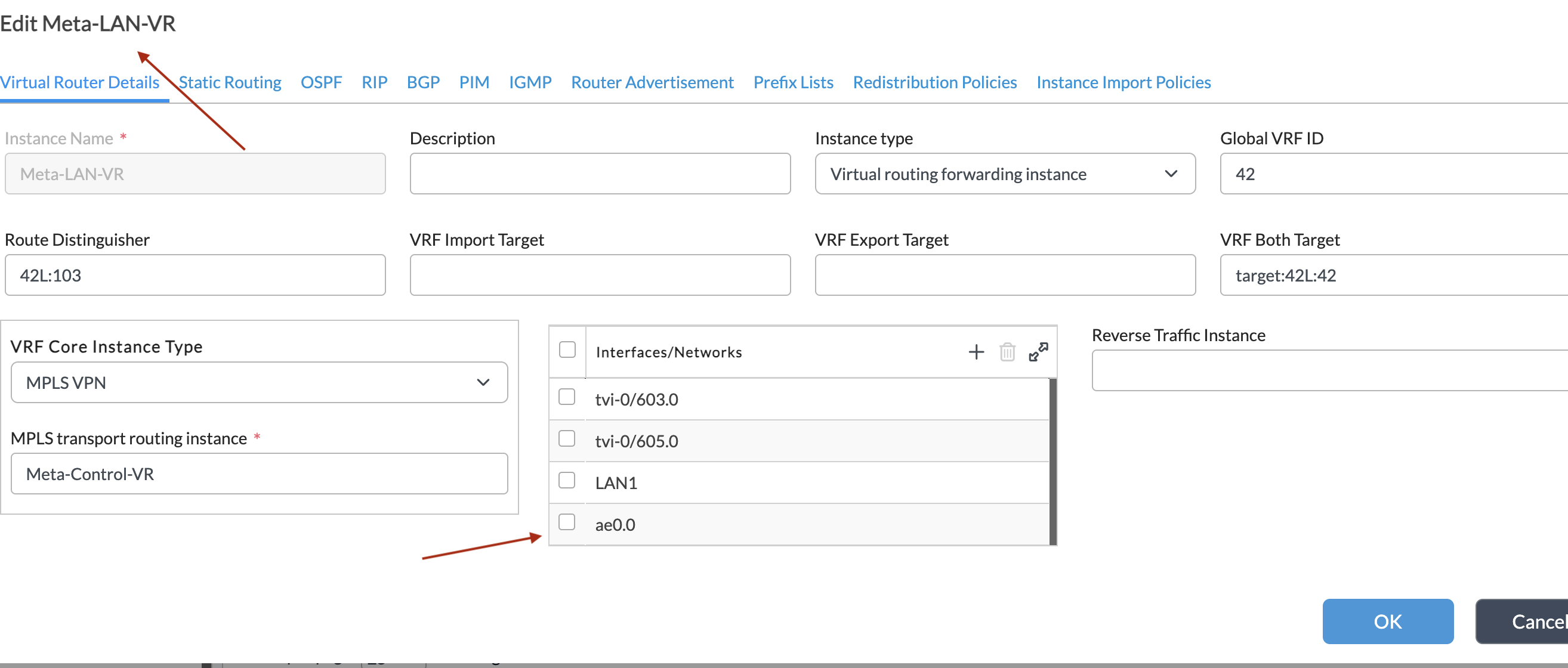
Navigate to the Virtual Routers tab.
Add the LAN network (with AE) under the correct Virtual Router.
Commit changes so they propagate to the appliance.
Method 2: Configuring LACP in Appliance Context
For standalone or quick deployments, you can configure LACP directly in the appliance context under Configuration > Networking > Interfaces > AE. This is useful for testing or when applying unique configurations not shared via templates. However, this approach reduces scalability since changes must be performed on each appliance individually.
Verifying LACP Configuration Using VOS CLI:
- show aggregate-ethernet
Displays the status of AE interfaces, the aggregation protocol in use (e.g., LACP), and their associated member interfaces. - show lacp info interfaces
Provides detailed role information for each interface in the AE bundle, including Actor/Partner details, system priority, system ID, and port attributes.
show lacp interfaces
Displays LACP interface state, including synchronization, distribution, timeout, and activity mode (active/passive).
show lacp statistics
Displays counters and protocol-level statistics for LACP interfaces. This is useful for monitoring stability and detecting negotiation issues. (Note: No sample output provided in documentation.)CLI configuration:
admin@CPE1-cli> show configuration interfaces vni-0/1
enable true;
promiscuous false;
ether-options {
aggregate ae0;
link-speed auto;
link-mode auto;
}
[ok][2018-11-28 18:31:33]
admin@CPE1-cli> show configuration interfaces vni-0/2
enable true;
promiscuous false;
ether-options {
aggregate ae0;
link-speed auto;
link-mode auto;
}
[ok][2018-11-28 18:31:37]
admin@CPE1-cli> show configuration interfaces ae0
enable true;
promiscuous false;
unit 0 {
enable true;
family {
inet {
address 173.10.10.1/24;
}
}
}
aggregated-ethernet-options {
lacp {
lacp-mode active;
system-priority 127;
periodic slow;
max-links 16;
}
}
Verification:
[ok][2018-11-28 18:03:04]
admin@CPE1-cli> show lacp interfaces
AE MEMBER
NAME INTF ROLE EXP DEF DIST COL SYN AGGR TIMEOUT ACTIVITY
---------------------------------------------------------------------------
ae0 vni-0/4 Partner No No No No No No slow Passive
ae0 vni-0/4 Actor No Yes No No Yes Yes slow Active
ae0 vni-0/5 Partner No No No No No No slow Passive
ae0 vni-0/5 Actor No Yes No No Yes Yes slow Active
[ok][2018-11-28 18:03:55]
admin@CPE1-cli> show interfaces brief ae0.0
NAME MAC OPER ADMIN TENANT VRF IP
-----------------------------------------------------------------------
ae0.0 02:00:86:29:89:00 up up 0 global 173.10.10.1/24